Hardware
Feather Carrier Board
- Depending on the Feather used, pinouts vary:
- Special Pins:
- A1: Enable for DRV2605
- A2: Pushbutton on the side
- A3: RGB WS2812/Neopixel Output (ESP32: 21)
Qwiic Hapt Prototype

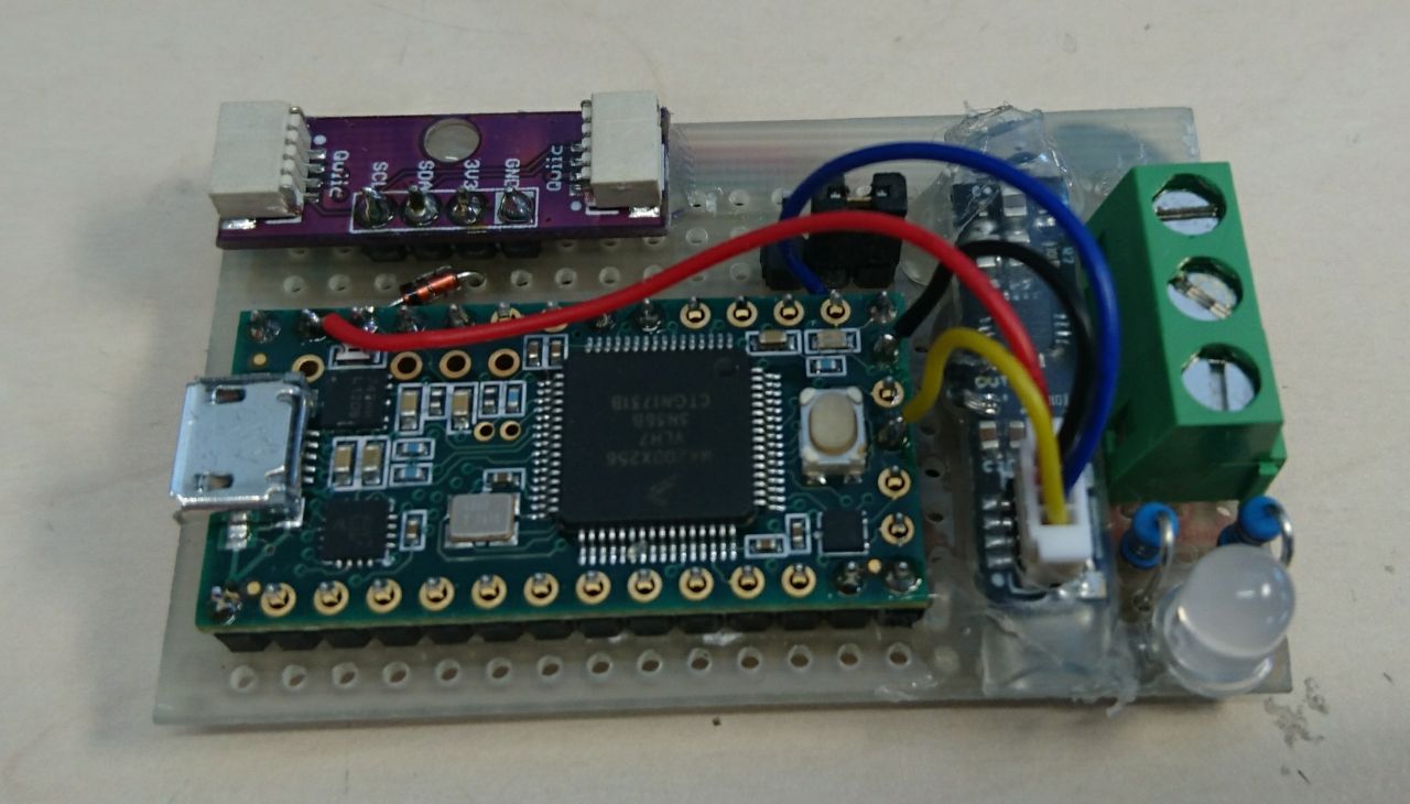
This device is made for testing a future hapt that can be driven directly from the I2C bus. It contains a Teensy 3.2 and an amplifier. Periphery are two Qwiic ports and a dual-color LED.
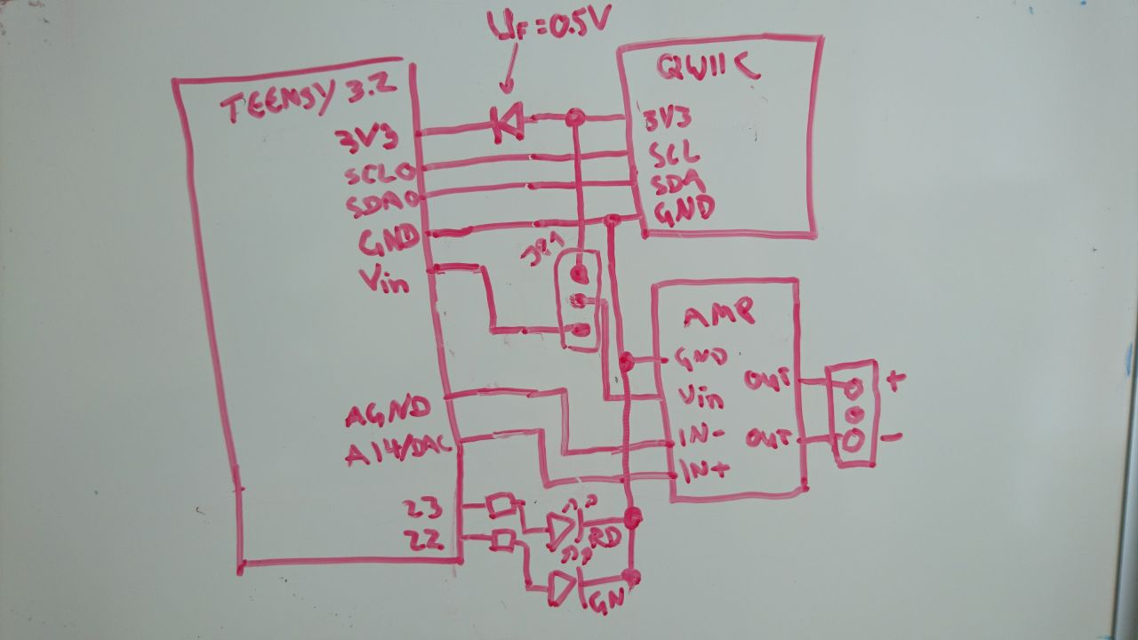
A jumper select between powering the amplifier via USB through the Teensy (for standalone testing, amplifier will run on USB voltage!) or via the Qwiic bus (3.3V). If the Qwiic bus is connected, the Teensy will also be powered by the bus through a diode. This leads to lightly increased operating voltage on the Teensy (2.8V), which is well over the minimum operating voltage of the microcontroller (1.7V). Keep in mind that this will also lead to reduced I/O voltage levels (2.75V), which however still easily comply to 3.3V TTL levels (https://learn.sparkfun.com/tutorials/logic-levels/all#33-v-cmos-logic-levels). Through the diode protection, plugging the Teensy into a USB port and powering it through the Qwiic bus at the same time is possible. Keep in mind that the Teensy will still be powered by the Qwiic bus even when the jumper is completely removed.
Keep in mind that the Qwiic Hapt prototype can be a bus master if programmed accordingly, but can not power the qwiic bus on its own. In this case, the bus has to be powered externally (3.3V).
The I2C port of the Teensy is connected to the Qwiic bus. Pullup resistors are not available on the Qwiic Hapt prototype. The red component of the dual-color LED is connected to pin 22 of the Teensy, the green component is connected to pin 23. The In+ input of the amplifier is connected to the DAC of the Teensy (pin 14). In- of the amplifier is connected to AGND of the Teensy.
